Défauts courants et entretien des pompes à engrenages
1.bruit excessif 2.manque de stress 3.fluctuation du trafic 4.température trop élevée de la pompe 5.fuites internes
Voir les détailsrecherche Search the whole station
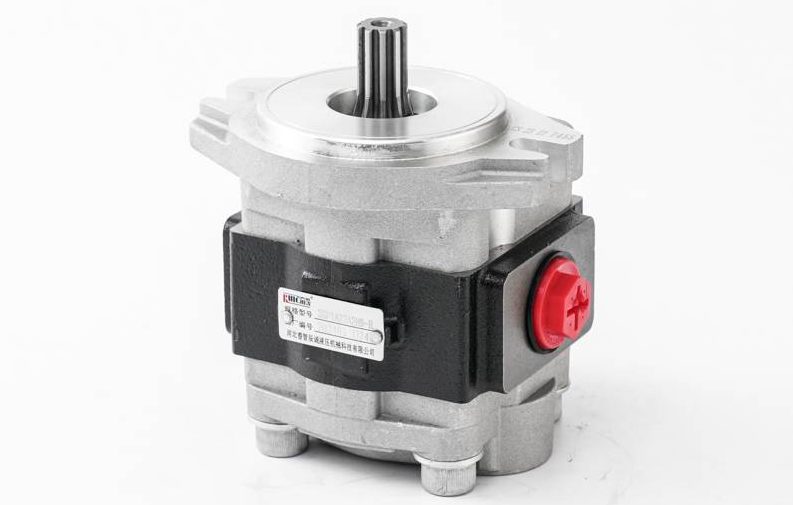
Cast iron gear pump is a common hydraulic component. Its internal structure is relatively simple, but powerful, suitable for various industrial occasions. The following is the main internal structure of the cast iron gear pump:
The core components of the gear pump are composed of two meshing gears: the driving gear and the driven gear. Usually the two have the same size and number of teeth.
The driving gear is connected to the drive shaft of the pump and is driven by an external power source (such as a motor) to rotate; Driven gear is rotated by the driving gear.
The rotating motion of the gear produces the suction and discharge action of the pump, and the liquid in the pump is pushed from the suction inlet to the discharge outlet with the rotation of the gear.
The pump body of the cast iron gear pump is usually a housing made of cast iron, which is used to support the gear and withstand internal pressure and external load.
There are two gear cavities in the pump body to accommodate the rotation of the gears.
The front and back end covers of the gear pump seal the two ends of the pump body, and together with the pump body form the working cavity of the gear.
The end cap also usually acts as a seal, preventing liquid leakage.
Bearings and Shaft Seals: Bearings and shaft seals:
The shafts of the driving gear and driven gear extend to the outside through the pump body, and the support of these shafts is usually achieved by bearings.
Shaft seals are used to prevent liquid leakage at the rotation of the shaft, usually with mechanical seals or lip seals.

The pump body is provided with an inlet and an outlet for liquid entry and discharge respectively.
The suction and discharge outlets of the gear pump are usually designed as standard flanged or threaded connections to facilitate the connection of the pipeline.
Some gear pumps are integrated with a bypass valve, which is used to prevent the pump outlet pressure from being too high to protect the safety of the pump and the system. When the pressure exceeds the set value, the bypass valve opens, and part of the liquid is returned to the suction end to reduce the pressure.
1.bruit excessif 2.manque de stress 3.fluctuation du trafic 4.température trop élevée de la pompe 5.fuites internes
Voir les détailsPompe à engrenages haute performance : le modèle industriel de stabilité et de fiabilité332/F9030, 333/G5390 et 20/903200 pompes à engrenages avec d'excellentes performances hydrauliques et une grande stabilité, largement utilisées dans les machines de construction et les machines agricoles et...
Voir les détailsLes activités de notre société comprennent : les services techniques, le développement technologique, le conseil en technologie, les échanges de technologie, le transfert de technologie, la promotion de la technologie ; la recherche et le développement d'équipements mécaniques ; la re...
Voir les détails
BonjourVeuillez vous connecter